racknex UM-SBC-209 + TI LP5012
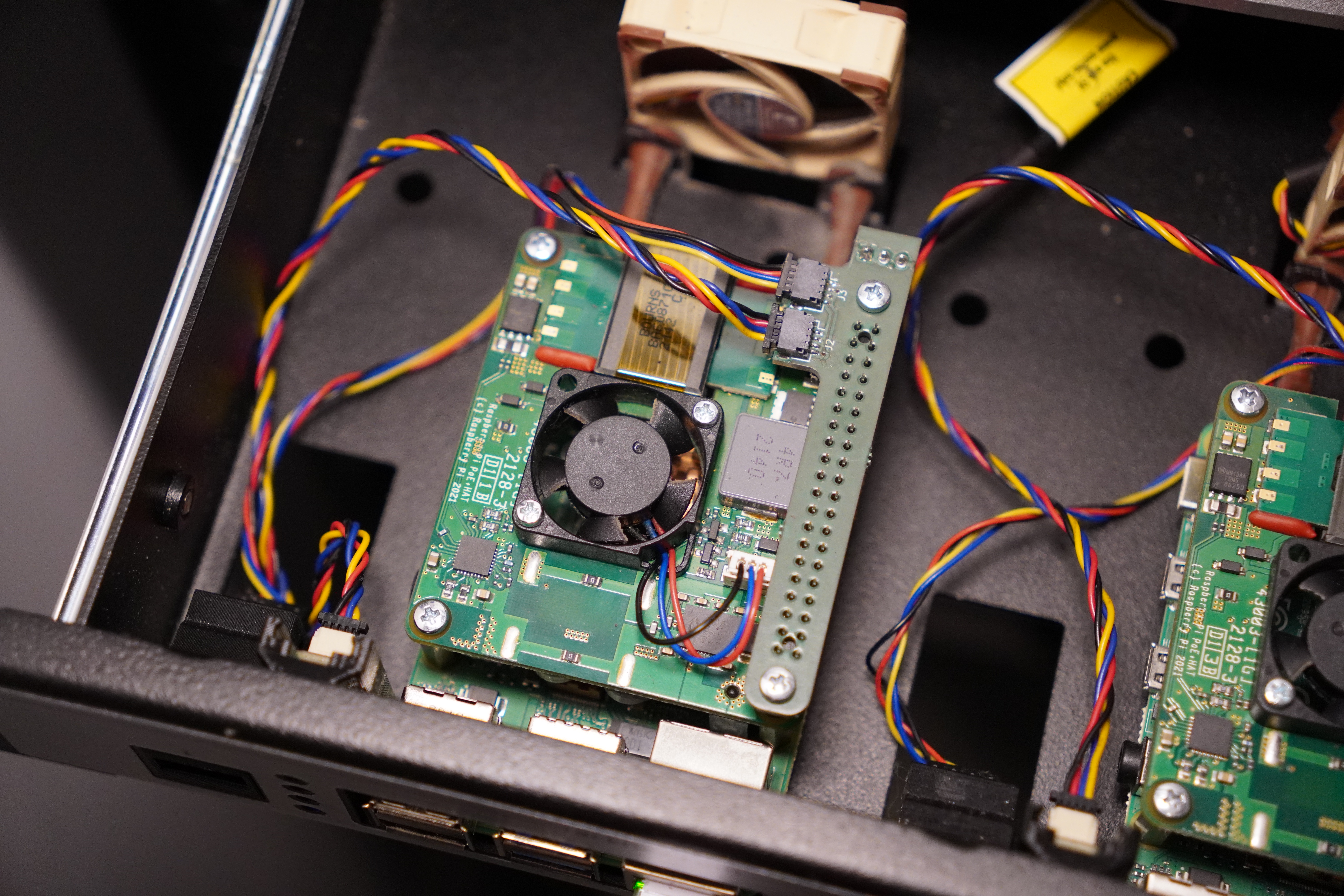
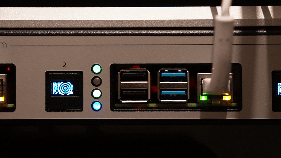
As you might have seen from my previous post, my RPi cluster is housed in a racknex UM-SBC-209 case. It's a great case that I utilized to the max by setting up my RPis with poe+ hats, custom hats that I made to expose i2c via two qwiic (jst sh) connectors and an additional 5v fan header that I use to connect to Noctua NF-A4x10 5V fans. I had made keystone holder for a tiny OLED display and had it connected via the same Qwiic connectors. The only thing left untouched were the holes for the LEDs.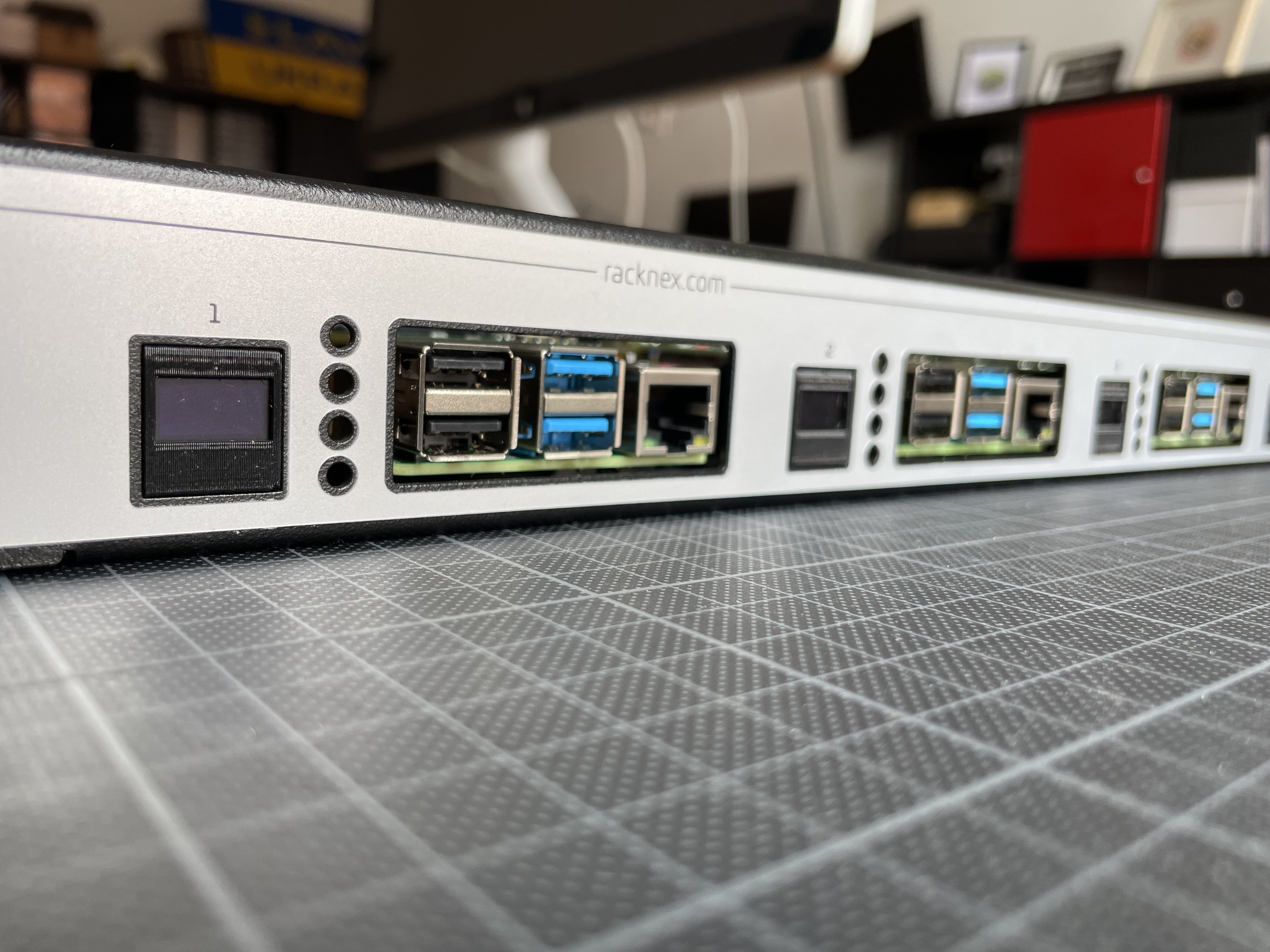
I wasn’t keen on wiring 3mm LEDs directly to individual GPIOs on the board. That's why my Qwiic hat was designed with two connectors instead of just one, though the second connector had been sitting idle for quite some time.
Finally, I decided it was time to put it to good use.
Electronics§
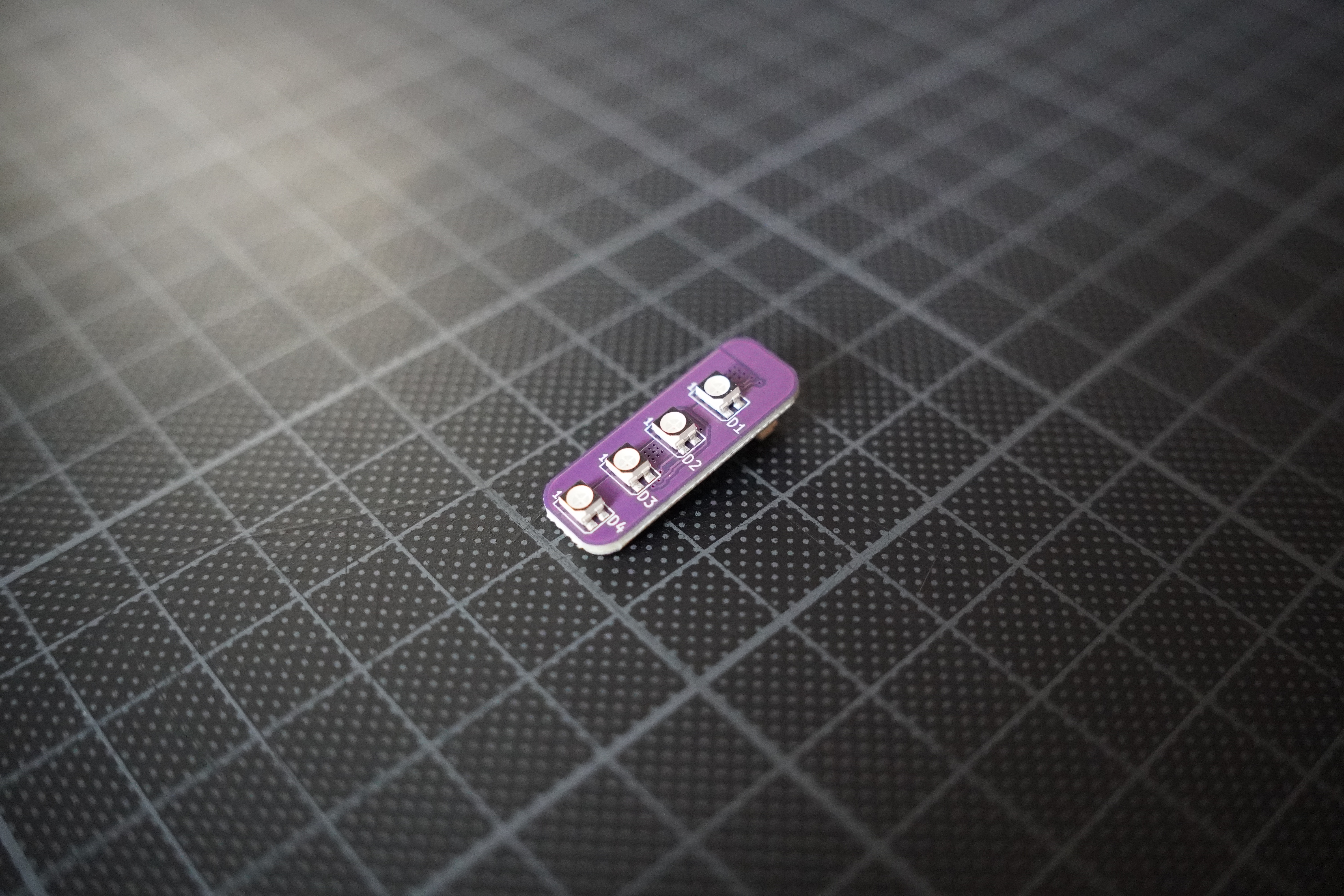
First off, I found a led controller. The TI LP50xx seemed like a great choice, since:
- it's driven through i2c
- the LP5012 supports up to 4 RGB LEDs
- the linux kernel has had a driver for it for years now.
I went ahead and designed a simple board for it, and there's not much to say about except that it's now open source.
When making a board this time around, instead of soldering components onto the board myself like I usually do, I took a gamble on the first revision and ordered it assembled by JLCPCB instead of assembling it myself.
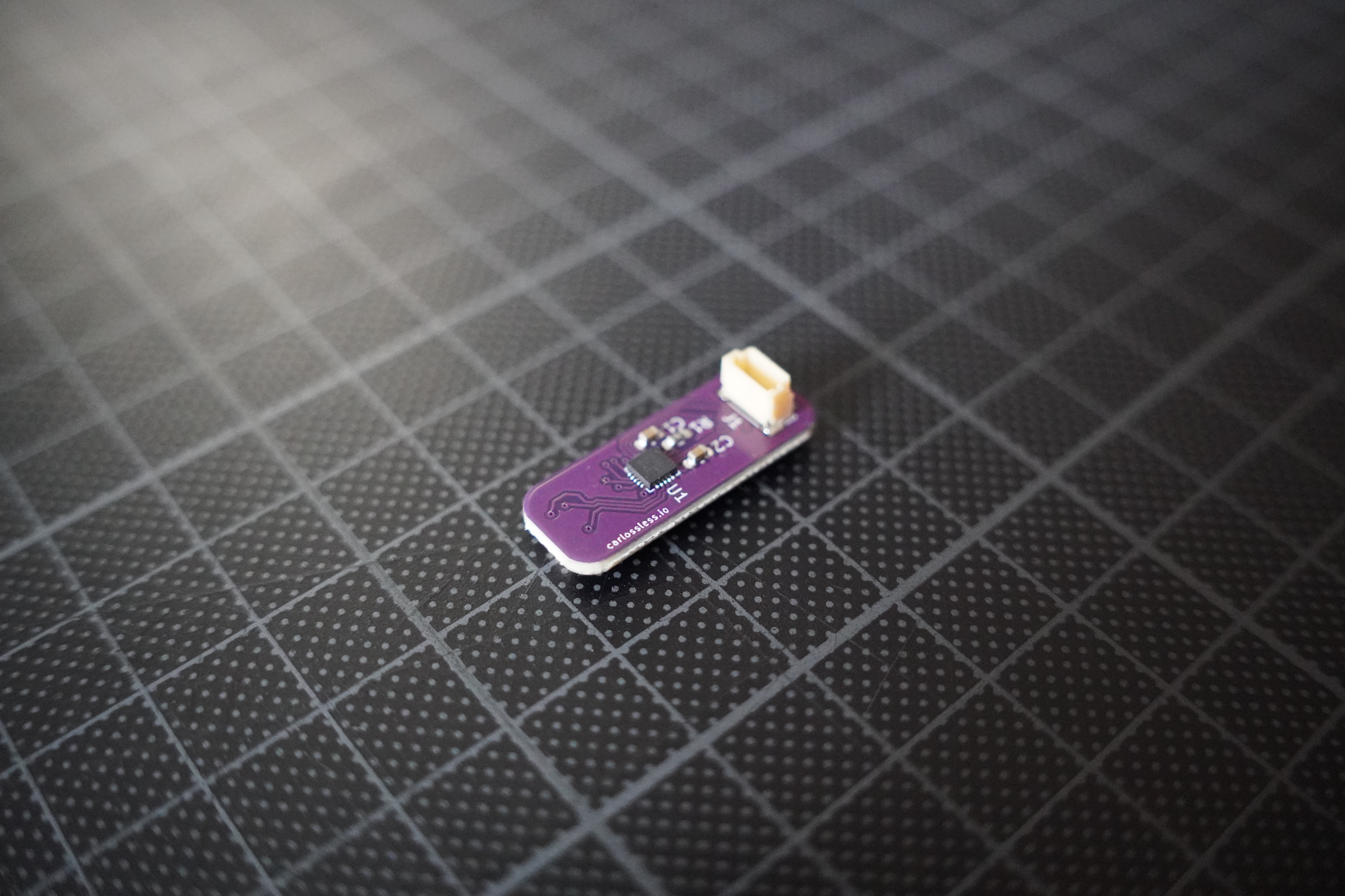
Surprisingly, everything worked on the first try!
A big shout-out to the maintainers of i2c-tools. This toolset was invaluable for quickly verifying that both the controller and LEDs were functioning correctly before proceeding to load the kernel driver via the device tree.
Bracket§
Even though this board works perfectly, it can't just float in mid-air. It needs to be securely positioned to align precisely with the LED holes. To solve this, I designed a custom bracket that fits snugly between the keystone frame, the Raspberry Pi and the bends of the front faceplate.
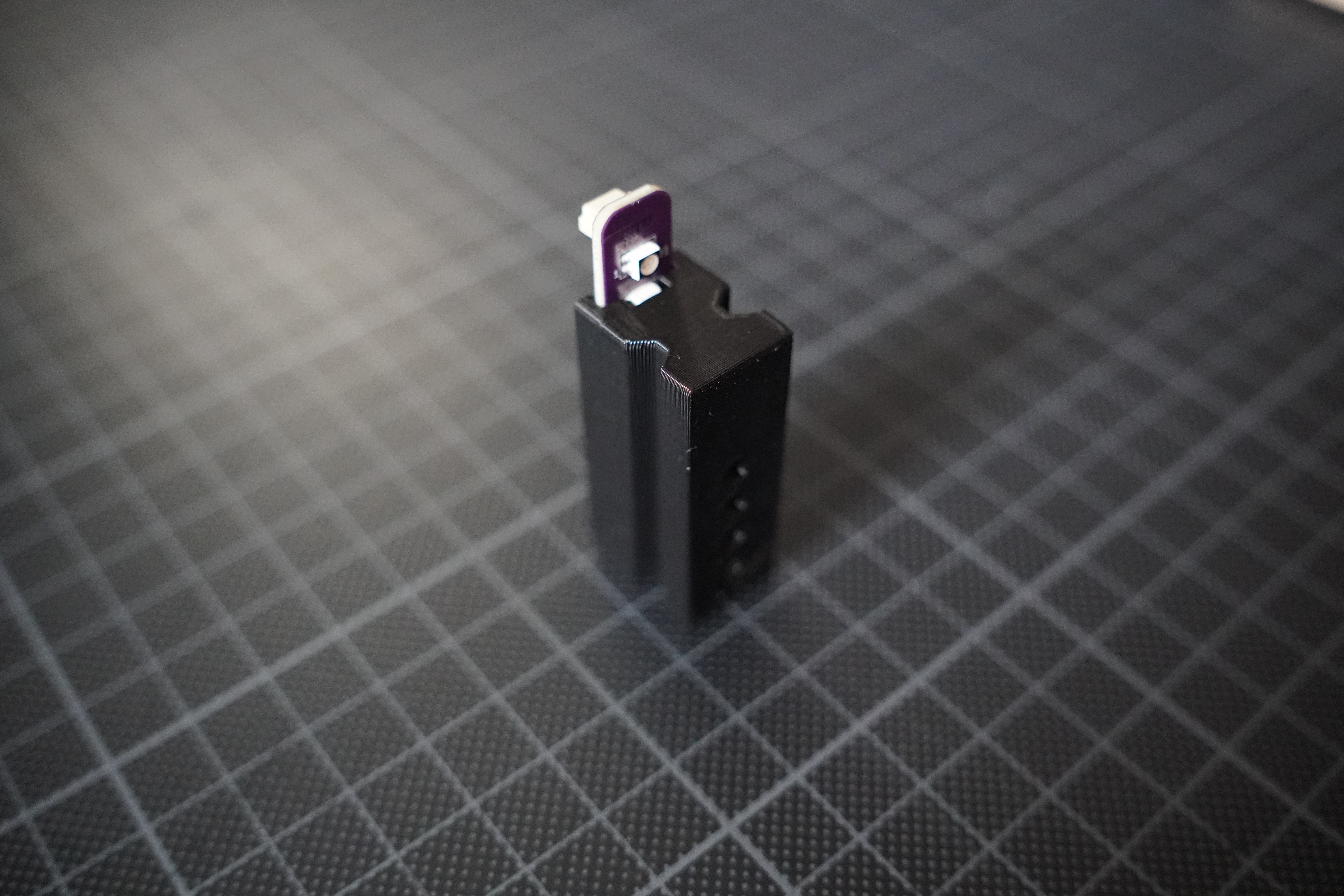
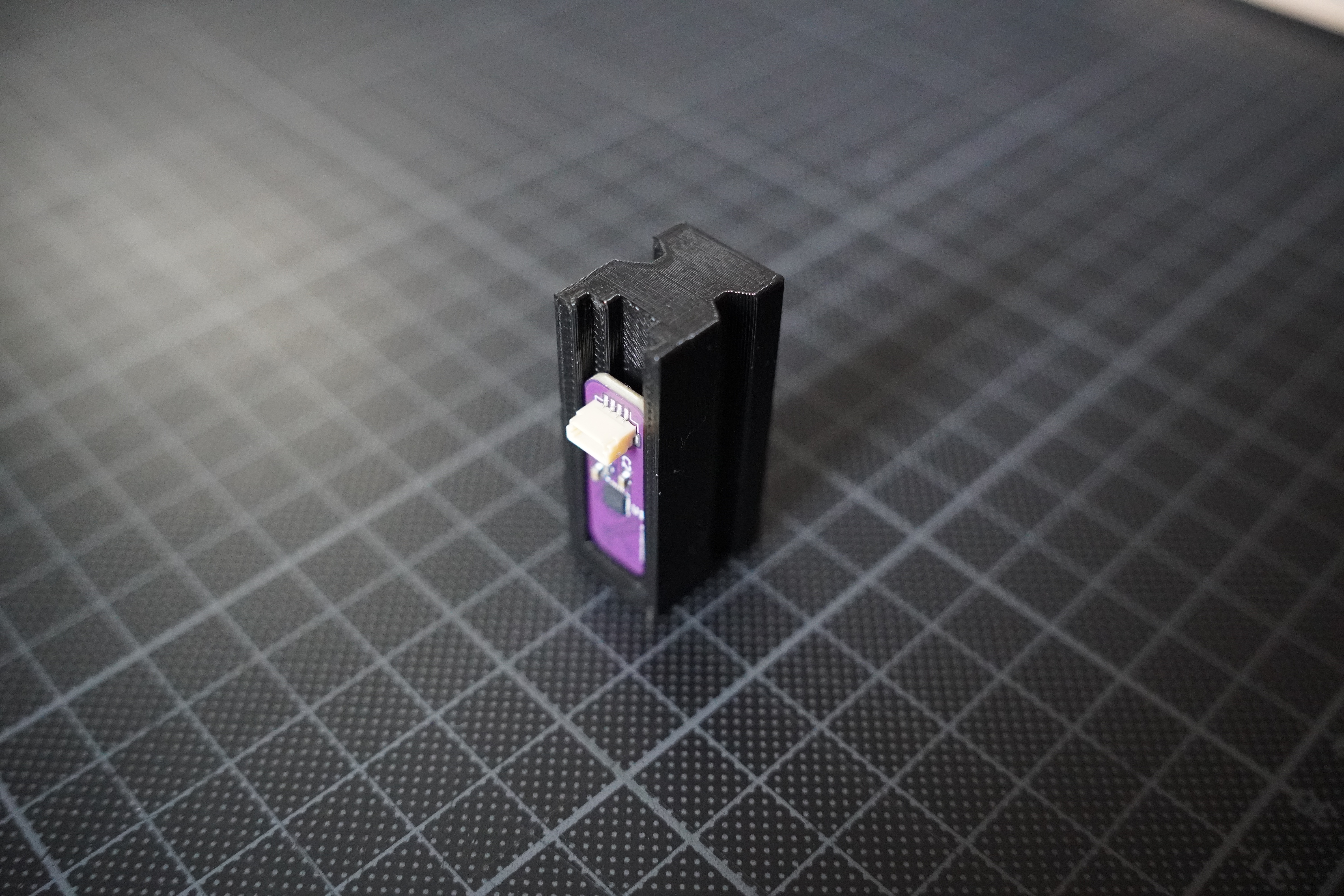
I also needed some light pipes to transfer and diffuse the light better, fortunately it was easy to find some on aliexpress.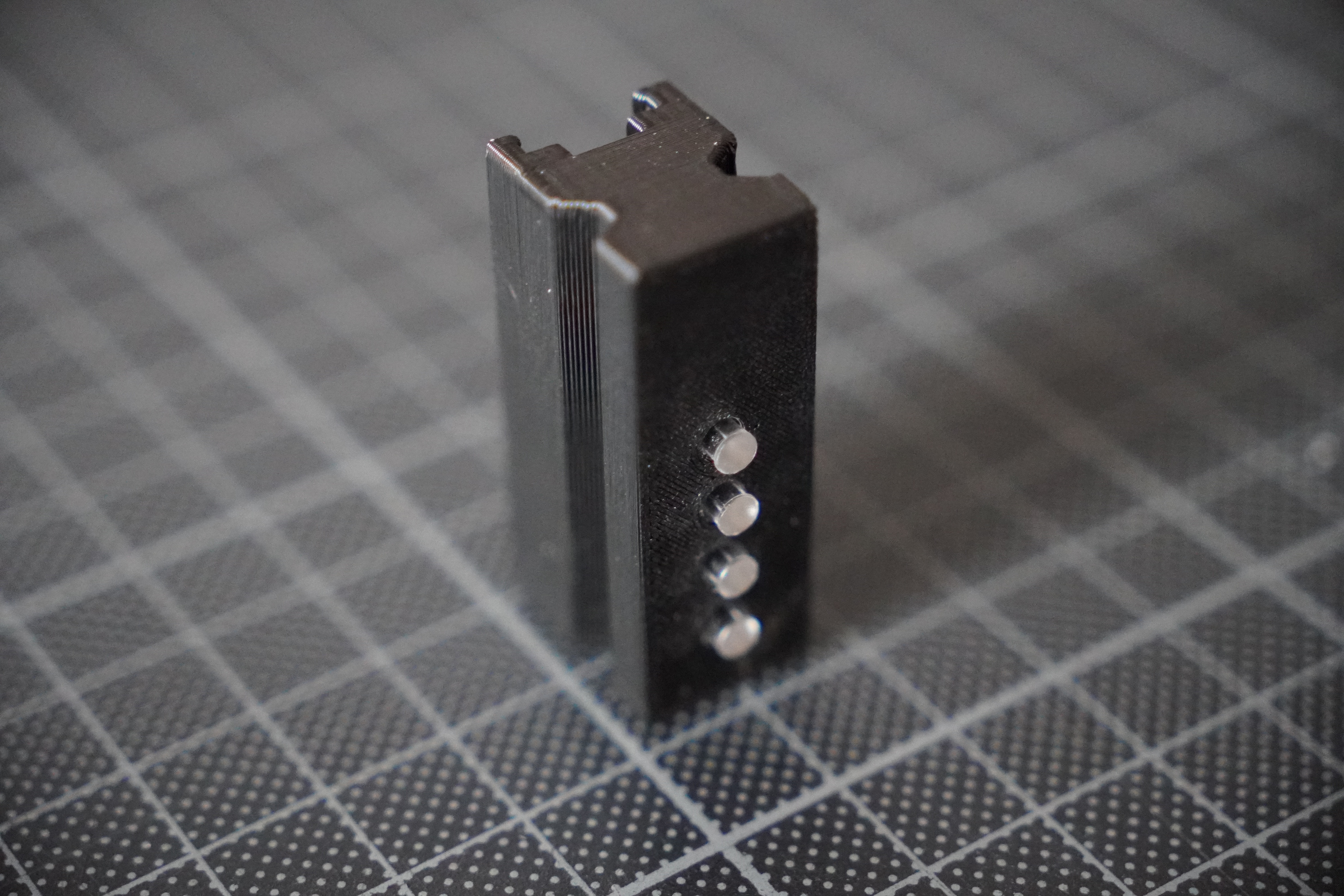
Configuration§
Now that I had everything ready, assembled, and installed, the final step was to build a device-tree overlay that would enable the kernel to drive these LEDs and make them actually indicate something. Fortunately, this was easy to do, and I ended up with:
/dts-v1/;
/plugin/;

#include <dt-bindings/leds/common.h>

/ {
  compatible = "brcm,bcm2711";

  fragment@0 {
    target = <&i2c1>;
    i2c_bus: __overlay__ {
      led-controller@14 {
        compatible = "ti,lp5012";
        reg = <0x14>;
        #address-cells = <1>;
        #size-cells = <0>;

        multi-led@0 {
          #address-cells = <1>;
          #size-cells = <0>;
          reg = <0>;
          color = <LED_COLOR_ID_RGB>;
          function = LED_FUNCTION_POWER;
          default-state = "off";
          linux,default-trigger = "default-on";
          max-brightness = <127>;

          led@0 {
            reg = <0>;
            color = <LED_COLOR_ID_RED>;
          };

          led@1 {
            reg = <1>;
            color = <LED_COLOR_ID_GREEN>;
          };

          led@2 {
            reg = <2>;
            color = <LED_COLOR_ID_BLUE>;
          };
        };

        multi-led@1 {
          ...
        }

        ...
      };
    };
  };
};
Unfortunately there currently is no way to set the initial color intensity through the device tree, so I had to do that via a oneshot systemd service:
{}: {
  systemd.services.lp5012-intensity = {
    enable = true;
    wantedBy = [ "multi-user.target" ];
    serviceConfig = {
      Type = "oneshot";
      User = "root";
      Group = "root";
      RemainAfterExit = true;
    };
    script = ''
      if [ -d /sys/class/leds/rgb:power ]; then
        echo "0 255 0" > /sys/class/leds/rgb:power/multi_intensity
      fi
      ...
    '';
  };
}
You can find the full nix module which includes the full device-tree overlay in this gist.
End§
And that's it, I finally feel this project is complete... for now...
You can find all the custom parts used in this project here: